RF Pigtail Test Probes
Available from .020 to .250 inch Coax Diameters
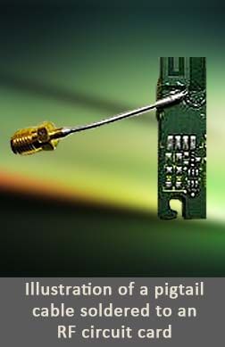
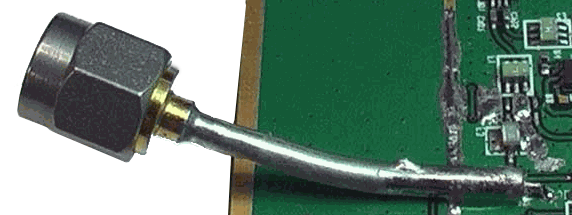
There are times when an RF design does not meet an expected RF circuit simulation and the only way to diagnose the problem is to perform in-circuit probing on a PCB. A good method for probing a circuit is by soldering a small diameter coax cable or RF pigtail on a PCB as a test probe, in order to inject an input signal or sample an output signal. Once tested, the soldered RF Pigtail test probe is easily unsoldered from the PCB.
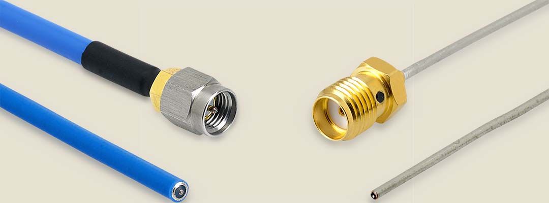
P1dB offers RF pigtail cables in coax diameters as small as .020 inches, with a center conductor diameter is .004 inches. This means that even a 0201 RF pad can be used as a test point by using a P1dB RF pigtail cable as a test probe. Pigtails are available in diameters from .020 to .141 and in semi-rigid, conformable, jacketed conformable or even flexible coax options. The most common RF Pigtail cable is an SMA Pigtail using either .034 inch or .047 inch semi-rigid coax diameters.
Pigtail Options
Choose a Connector and a Coax
Connector Options
Any connector can be chosen to build an RF Pigtail, as long as a connector is available for the desired semi-rigid, conformable or flex cable. The most common connector for RF Pigtail cable test probes is an SMA Female connector that operates up to 6 GHz or 18 GHz. Here is a short list of RF Pigtail cables that we have built using other connector versions and frequencies,
SMA Female Pigtail tested at 6 GHz and 18 GHz
SMA Male Pigtail tested at 6 GHz and 18 GHz
2.92mm Male Pigtail tested at 18 and 40 GHz
MMCX Male Pigtail tested at 6 GHz
SMP Female Pigtail tested to at 18 GHz
Other connectors and frequency options are available upon request
P1dB stocks the most common connector configuration, but if the desired connector is not available, then below are some more connector codes that can be used to build a Pigtail cable.
Connector Code Options
| SMA | 2.92mm | SMP | SSMP | MCX | MMCX | N | |
| Male | SAM | 29M | SPM | SMM | MXP | MMP | NM |
| Female | SAF | 29F | SPF | SMF | MXJ | MMJ | NF |
| Female Bulkhead | SAFB | 29FB | SPFB | SMFB | MXJB | MMJB | NFB |
Coax Options
RF Pigtail coax selection depends on the type of Test Probe that is required. For example, if a circuit trace is only a few
There are various coax options available, from semi-rigid, conformable, jacketed conformable and even flex cable. The most common choices are semi-rigid coax in either .034 or .047 inches in diameter, for the reason that the center conductor is still small enough to attach to small traces, yet not so small that it becomes difficult to trim the coax. Here are just a few of the coax options available:
Pigtail Coax Options
Coax Diameter
| Center Conductor Diameter, in. | Semi-Rigid | Conformable | Jacketed Conformable | Flexible |
| .020 (.51mm) | .004 (.10mm) | 020SR | |||
| .034 (.86mm) | .008 (.20mm) | 034SR | 034CC | ||
| .047 (1.19mm) | .011 (.28mm) | 047SR | 047CC | 047CJ | SS047 |
| .086 (2.18mm) | .020 (.51mm) | 085SR | 085CC | 085CJ | SS085 |
| .141 (3.58mm) | .064 (1.63mm) | 141SR | 141CC | 141CJ | SS141 |
| .250 (6.35mm) | .064 (1.63mm) | 250SR | 250CC | 250CJ |
Build an RF Pigtail Test Probe Part Number
There already is a large selection of RF Pigtail cables in our Pigtail Section, but in the event, the desired Pigtail does not exist, you can configure a part number by requesting a quote or by using a Cable Configurator. You may also build a part number using the following part-number convention,
zzz = length in inches
Using a Pigtail as an RF Probe is Simple
Use an RF Pigtail to Measure IC Performance or as an Antenna Feed
Preparing a Pigtail for use as a Probe
An RF pigtail probe is an excellent way to sample a signal within a circuit, without having to design-in test points into a circuit board. The effects of a pigtail, though, can influence circuit performance, depending on the trace width, circuit board dielectric, and thickness. The sensitivity of a circuit can be further impacted by the frequency, which may mean that the center conductor inductance (length) can negatively affect the RF signal. This may require that the RF pigtail is tuned for optimal performance within the location being tested. The best way to determine the best pigtail probe performance is by experimenting with different center conductor lengths to find the best match. As a rule of thumb, try to keep the lengths as short as possible.
1. Cut off the jacket and insulator to expose the center conductor.
2. Solder the coax shield to a nearby ground.
3. Solder the center conductor to the desired trace or pad.
4. Unsolder the coax when testing is complete.
A straight-cut RF pigtail is the most commonly used configuration, but it is not the only way to optimize a pigtail for a given circuit design. The pigtail can also be shaped in different ways to achieve an optimal match for a given circuit board transmission line. Here are a few examples of pigtail shapes and possible applications.
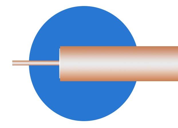
Straight Cut Terminated RF Pigtail
The straight cut is the simplest and most popular shape for a pigtail. It is most commonly used for microstrip boards.
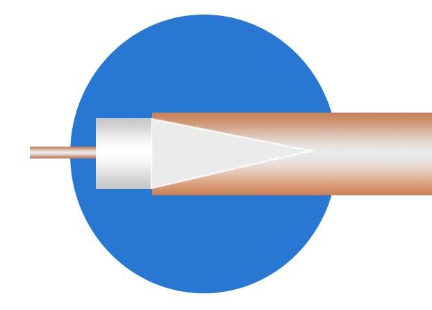
V-Cut Terminated RF Pigtail
The V cut is a bit more difficult to shape, but it can provide better matches. The V serves as a quasi-balun to help match to a transmission line. It can be made by using a Dremel tool to grind off the shield to form the V. The V cut is a good choice when trying to feed a co-planar waveguide circuit.
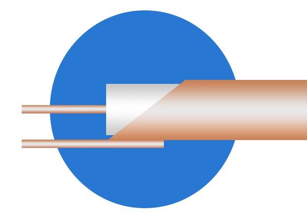
Twin Lead Terminated RF Pigtail
The twin lead cut is best suited for feeding antennas, such as a spiral. It is a good balun when transitioning to a twin lead, slot line or other parallel transmission line structures. It is more difficult to implement because it requires an additional wire to be soldered to circuit-trace ground and to the pigtail shield.


